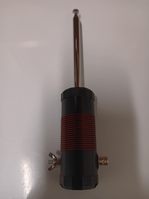
CalQRP SLQRP20 Antenna
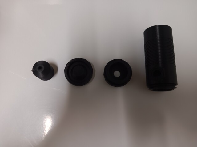
The antenna body parts are 4 pieces which are 3D printed (Printables and Thingiverse). The main body, the screw on base, a screw-on cap, and the antenna mount. All parts use plastic threads that allow for quick and easy assembly.
Thanks to CalQRP members Jonathan Poland, NØWL, and Doug Hendricks, KI6DS, for leading the design of this project. And J.C. Martin, W6IPA, for the original 3D printed design.
Parts
- ~11ft of 18 gauge magnet wire for 18 turns
- M4x25mm screw
- M4 nut
- #6 common x 1" screw w/ nut, wingnut etc for ground post
- BNC adapter
- Hillman 1/4-in x 20 Brass Wood Insert Nut
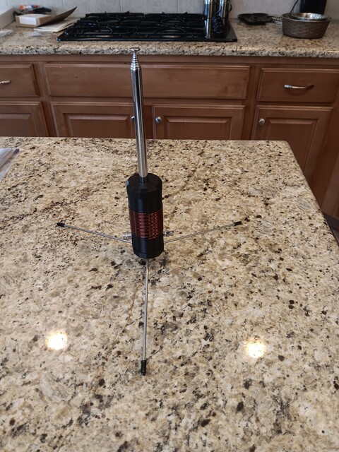
- this is an easy & sturdy tripod mount - 3x 1/8" steel rod for Tripod legs
Assembly
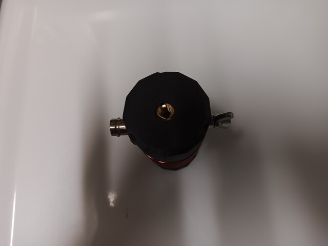
- You will need to glue with super glue the 3 black feet for the table mount.
- Assemble the Brass tripod mount in the base by screwing the brass 1/4-20 insert into the bottom.
- Assemble the antenna section by placing the M4 nut in the hex hole and place the M4 screw through the "pointy end" of the antenna support to engage the nut. As you tighten the screw, you will pull the nut into the plastic antenna support and will feel significant tension when the nut reaches its base.
- Solder a short (2") length of wire to the BNC ground ring and attach to the head of the ground post. Leave the ground ring and wire hanging out of the bottom hole.
- Attach the BNC cable mount, making sure that the ground ring goes against the inside plastic before the nut. This is the most fiddly step to accomplish because the stiffness of the ground wire tries to keep the ground ring from sitting on the BNC threads properly. Be patient and use good lighting. Tighten the nut with needle nose pliers.
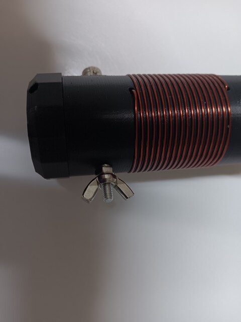
- Assemble the ground post onto the main body. (I find it easier to do at the beginning than after winding the coil).
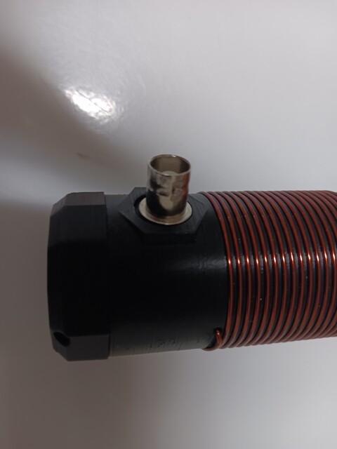
- Start winding the coil by first passing the wire though the top hole of the coil body and out through the center hole where the antenna will sit. Remove insulation from the end of the wire and attach to the head of the M4 screw. Then pull all slack out of the wire and seat the antenna mount onto the coil body. Now is a good time to screw in the upper retaining ring.
- Wind 18 turns of wire around the coil base - WITH NO SLACK IN THE WIRE. Feed any remaining wire into the small hole at the bottom of the coil and pull tightly. Folding the wire against the inside of the coil will keep enough tension on the wire that the coil will not slip.
- Cut the wire as short as you feel comfortable. I leave about 3/4" out of the base. Strip the end and solder to the center of the BNC adapter.
- Screw in the base.
More pictures
 |
 |
 |
 |
 |