VK3IL Pressure Paddle
VK3IL's design has two size available: a short 63mm long and a longer 100mm model.
The shorter model is a bit more packable but some ops say it needs just a bit more to hold onto.
The longer model is a bit more to grab onto and easier to hold for some ops.
They are otherwise exactly the same design and build and it comes down to personal preference.
Order
At present, we have a very limited number of kits available. (Only 16 left at time of writing) When they sell out, I will disable the order button.Kits for this build are available for $30 (US shipping included) To minimize and simplify costs/fees, shipping is only available for US addresses at this time.
Construction
There's not a lot to this kit. The parts are small (almost all SMD), but it can be assembled in under 10 minutes. Because the parts are small, SMD components, you will need plenty of good lighting and a soldering iron with a very fine tip. Personally I found it was helpful to have a flux pen to help the components adhere to the pads when placing them. I also held them in place with a toothpick while soldering the first pad.I managed to build my first two paddles with small USB-C soldering irons available on Amazon for ~$15.
The following steps are mere suggestions. Because of the simplicity, you could probably look at the images provided here and be just fine.
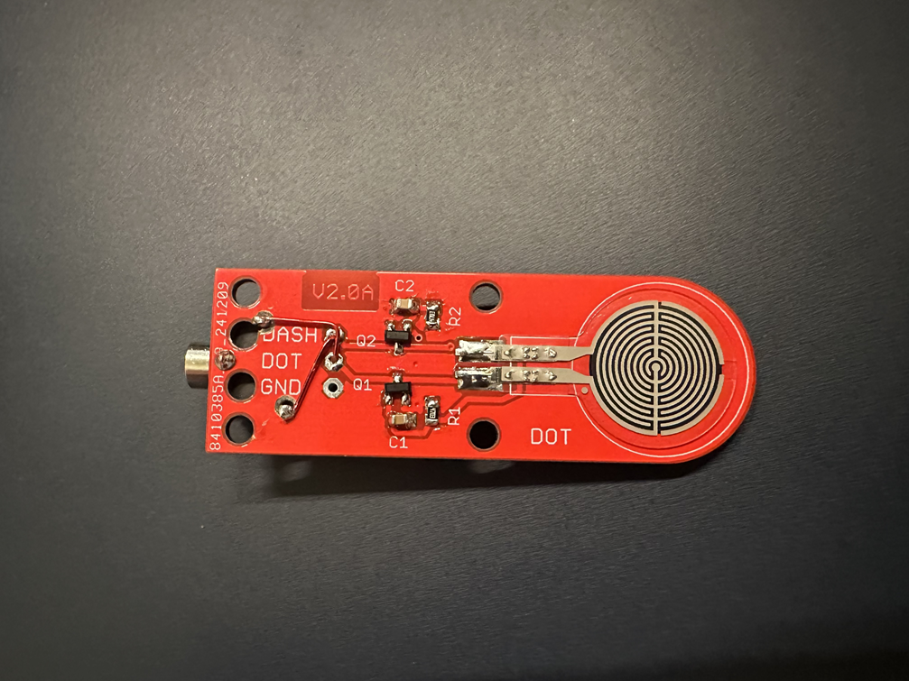
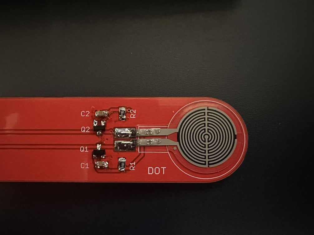
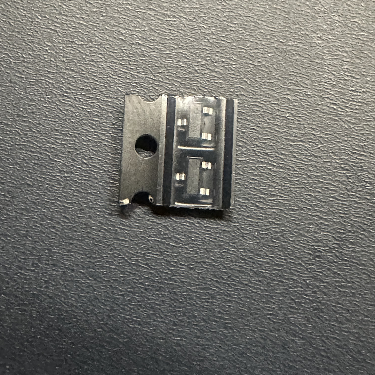
- Identify the MOSFETs. These are the easiest to spot because they're the ones with 3 legs. Solder the transistors onto the pads at Q1 and Q2.
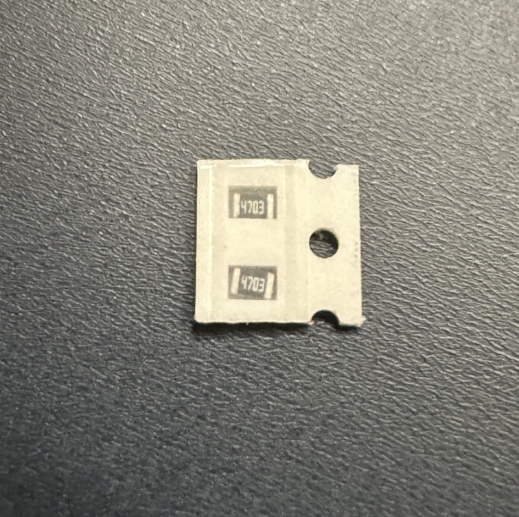
- Identify the resistors. (They are marked with the 4703 number) Solder the resistors on the pads at R1 and R2.
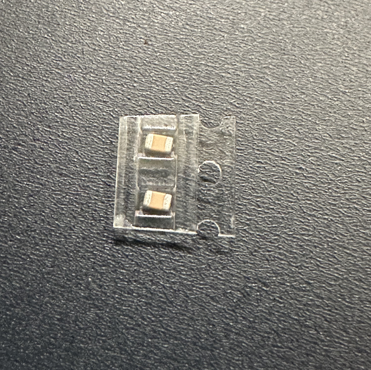
- Identify the capacitors. (These are the beige devices with no markings. Though this could change in the future.) Position and solder them onto the pads at C1 and C2.
- Carefully peel back the adhesive backing paper on the touch sensors and position the sensors in the circle spaces on the PCB. The leads of the sensors will align to the far edge of the pads on the PCB. Take your time and align them straight to avoid any frustrations later! Solder the leads in place.
- What's left is to decide which connection to your cable you would prefer.
You can either:- directly solder a TRS cable of your choice to the appropriate pads on the PCB, or...
- drill 3 holes to accomodate the included 3.5mm jack flush with the PCB
- Included with the kit is a length of shrink wrap. Once the paddle is constructed and operating as you like, slide the shrink wrap over the components and apply heat to shrink it in place.
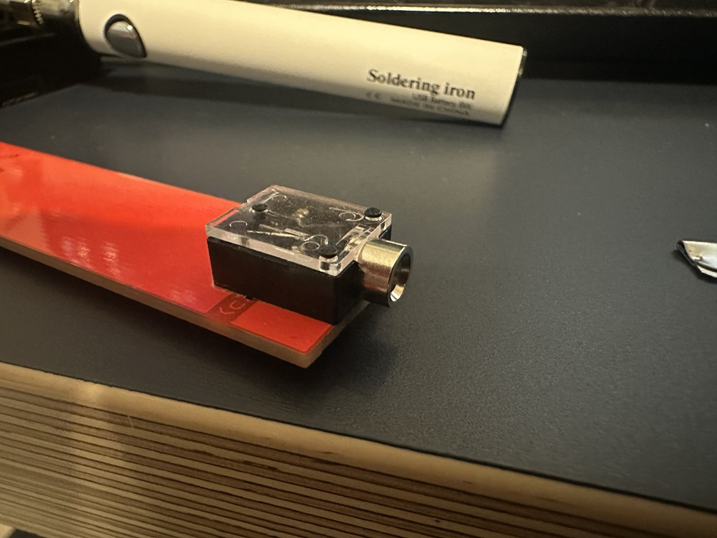
Mounting 3.5mm jack
I hope to modify the original Gerber files to accomodate the 3.5mm jack directly on the board so you won't have to drill these holes. In the meantime, here's how I positioned the holes: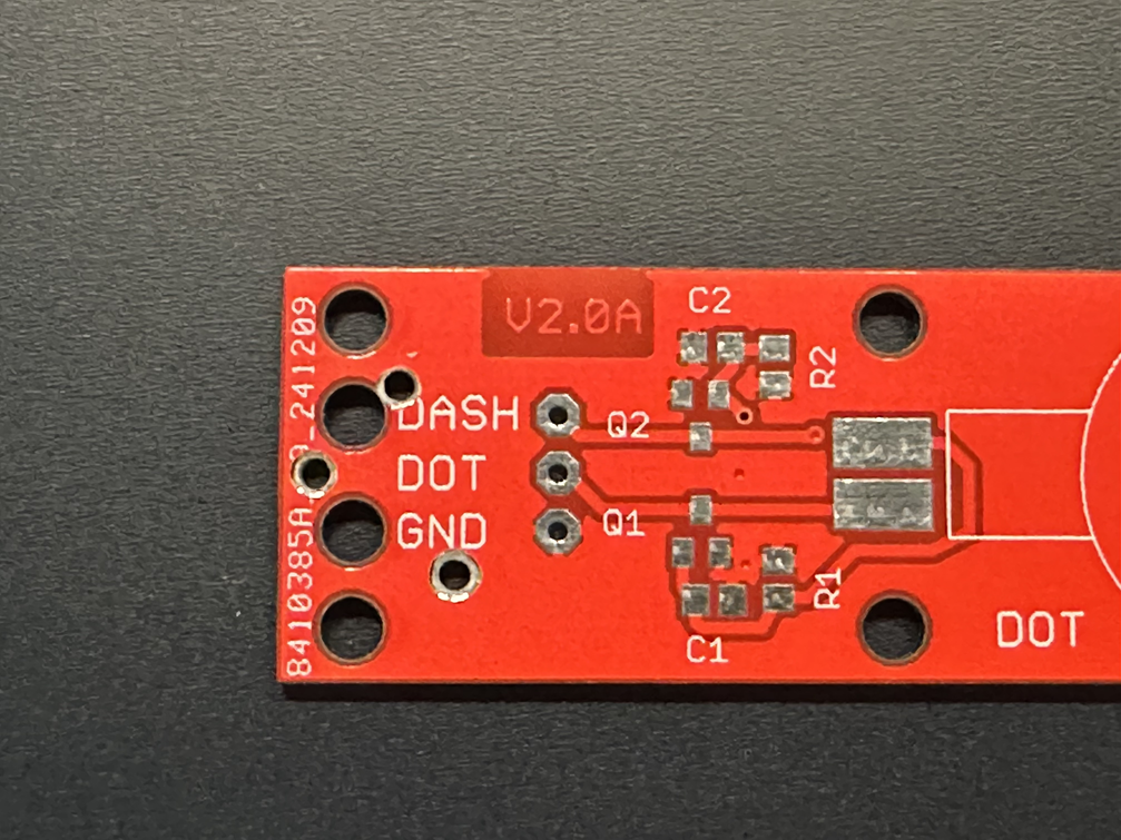
- Near the edge of the board is a small via for the PCB ground plane. It is very tiny, but this can be drilled out with a small 1/16" drill bit to serve as the ground connection on the audio jack.
- For the ring connection, I found a point right at the very tip of the V in the VK3IL printed on the PCB.
- For the sleeve connection, it is less exact. By trial fitting the other pins in their respective holes, you can locate a position between the 1 and 2 o'clock positions in the 2nd (from the top) strain-relief holes in the PCB.
Consult the image to the side for a better idea of where this will be. - I also found it helpful to go back with a slightly larger drill bit and ever-so-lightly and shallow "countersink" the holes (especially the ground pin, you want it to make good solder contact with the groundplane on the PCB.)

3.5mm jack mounted - Some have glued the jack into place then soldered the connections. Personally, I've found it sufficient (thus far) to simply solder the ground pin and let the connecting wires hole the jack in place. If this changes, I'll come back and update these directions!
- Cut two or three short lengths of insulated wire to connect the tip, ring, and sleeve connections on the 3.5mm jack to the appropriate pin on the PCB.
I found enamel coated wire works well and adds nothing in terms of bulk to the construciton - but use what you have. - I personally could never remember the pinout for CW paddles (if you have an good, easy mnemonic to remember, shoot me an email!). So, for your reference:
- TIP connects to dit
- RING connects to dah
- SLEEVE connects to ground